Load Takedown Worked Example
2025-09-25
Load Takedown Worked Example
This post runs through a simple, manual method to estimate the loads that reach a building’s foundations. It’s intended as a quick check or a way to validate your structural model — or for conservative design loadings on very simple structures.
As always, assumptions should lean on the conservative side.
1. What is load takedown?
A load takedown (sometimes called a load path or rundown calculation) is the process of following how applied gravity loads move through a structure down to the foundations.
Every roof, floor, and wall applies forces that must eventually be carried into the ground. Understanding this path early helps engineers size foundations, anticipate problem areas, and avoid surprises later.
2. Why estimate foundation loads?
Running a hand calculation of foundation loads during concept design provides several benefits:
- Helps decide which foundation types are feasible.
- Flags potential ground issues that might require strengthening.
- Gives a quick check on cost implications of different schemes.
- Acts as a reality check against your structural model.
Sometimes a quick load estimate shows that a scheme is not viable or cost-efficient. It’s better to know that early, even if it means revising the concept. Clients often appreciate the honesty.
As a rule of thumb, it’s good practice for every engineer to carry out a manual load takedown before committing to full detailed design.
3. Assumptions for simplified load calculations
To keep the process manageable, we’ll use the following assumptions:
- Horizontal loads are not considered (assumed supported separately).
- Conservative load values from codes/national annexes.
- Floors are simply supported.
- Wall openings are ignored, except where critical.
These simplify the numbers without losing too much accuracy for a first-pass estimate. Always record assumptions alongside your sketches/calculations for future reference.
4. How loads transfer through a structure
Loads follow predictable paths:
- Floors → Beams
- Beams → Columns or Walls
- Columns/Walls → Foundations
- Foundations → Soil
It helps to picture the structure as a chain of simple load paths. For example: a one-way spanning slab feeds beams, beams feed columns, columns feed the foundation. Breaking it down makes manual load takedown far less intimidating.
5. Factored vs unfactored loads
Structural loads fall into two categories:
- Dead loads (permanent) → self-weight of structure.
- Live loads (imposed) → occupancy, furniture, snow, etc.
Whether you use factored or unfactored loads depends on what you are designing from the takedown results (e.g. foundation checks vs sizing vertical elements).
For a broader overview of foundation types, check out Building foundations (Designing Buildings Wiki).
6. The worked example
We’ll consider a simple two-storey house with a flat roof, typical in the UK. For a structure of this size, a manual takedown can be sufficient for preliminary foundation design.
Step 1 — Floor plan markup
The figure below shows the house floor arrangement and the spans of the floors. Always mark these up as a first step.
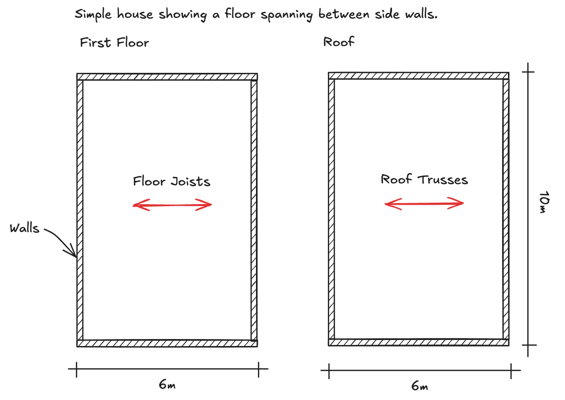 House floor arrangement and floor spans.
Step 2 — Section markup
A section through the house shows wall and foundation arrangements, plus applied floor/roof loads. For simplicity, assume the floor and roof loads are the same. The ground floor is self-supporting and excluded.
 Section through the house showing floor and foundation arrangement.
Step 3 — Consider a floor span
Pick a floor. Identify the span and the supporting walls. The tributary area (loaded width) is half the span length each side.
 Tributary area concept — loaded width passing to supporting walls.
Step 4 — Beam formula
For a simply supported span, the load on each wall is:
Wall reaction = w × L / 2
Where w = area load (kN/m²), L = span length (m).
 Beam formula for converting area load to line load at supports.
 Beam formula for converting area load to line load at supports.
Step 5 — Line loads at foundation level
Next, calculate the line loads from each floor and roof, then transfer them down to the foundation.
 Line loads at foundation level after floor and roof reactions.
Step 6 — Add wall self-weight
Finally, add the self-weight of each wall to the loads from the floors. This gives the total line load at the base of the wall.
 Wall self-weight combined with tributary loads at foundation level.
7. Use the results
Now the foundation line loads can be marked up for use in:
- Preliminary foundation design.
- Comparison against analysis model results.
- Checking scheme viability.
It’s crucial to record key inputs (spans, loads, assumptions) so others can check the work later.
 Final markup of calculated loads ready for foundation design.
8. Key takeaways
- Keep assumptions simple but conservative.
- Always record assumptions, loads, and results clearly.
- Manual takedown is quick, transparent, and valuable — even in the age of software.
- A free load takedown spreadsheet can help you structure these calculations in a reusable template.
This worked example demonstrates how manual load takedown can guide foundation design decisions. For larger or more complex projects, software tools can speed up the repetitive parts while preserving the clarity of this step-by-step approach.
9. Next steps
If you find yourself repeating these hand calculations for every project, there are tools that can speed things up:
- Start with a spreadsheet — our free load takedown spreadsheet lets you input floor loads and tributary areas in a structured template, ready for permit submission.
- Move to the app — when projects get more complex, LoadTakedown lets you sketch structures directly on PDFs, assign loads, and get tributary load results instantly.
Manual load takedown is a fundamental skill for engineers. Keep it sharp, but don’t be afraid to let software speed up the process when projects get bigger.